April 2001 ...
April 8th, 2001
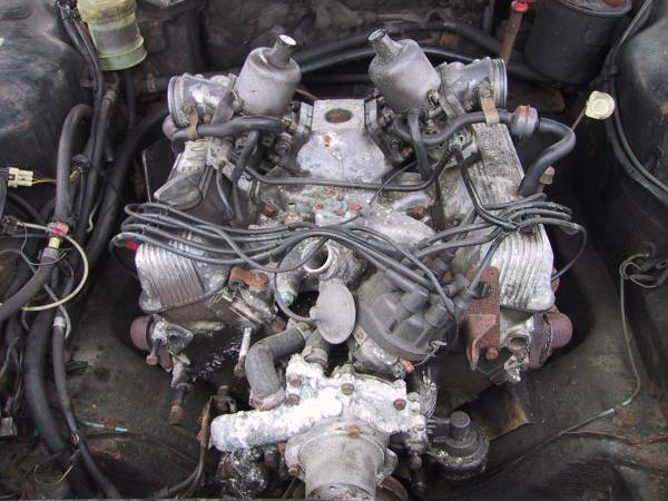
Really went 'balls out' to get the 3.5 out of the P6 and after a solid day's scrabbling around under the car, the engine was persuaded to come out complete with gearbox. It was then just a simple matter of splitting the 'box from the engine and then removing the torque convertor and flywheel. The engine was then bolted to the shiny new engine stand bought especially for the job from Machine Mart.
![]()
April 13th, 2001
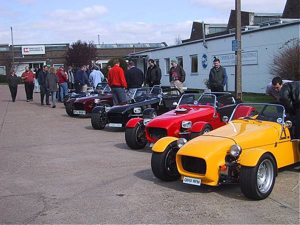
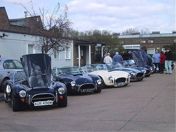
Set off for the Dax open day to try to put some cars to faces. Took my father along for the ride to show him what the pile of old cars at the back of his land was really for. He was quite taken with all of the cars on show but professed a bias towards our Tojero brothers' machines!! Bless him, he is getting on a bit!!
I took special interest in Ash's car (and several pictures) since it is very akin to that which I am attempting to build. I have to say that he's done a particularly fine job and his Rush is a credit to him. Unfortunately I was not able to speak with the man himself as he seemed rather busy flitting between the parts department and his car with bits of hood assembly.
Also saw Richard Pope there (SE DROC area secretary) but he seemed to have been cornered by a fellow 'enthusiast' and after an hour or so of hoping that I might get a chance to chat, Dad and I gave up and called it a day. Suitably uplifted however, we set off back to Kent to set about the P6 engine.
On the way home spotted Tim and Duncan on their way to the factory. Never mind, maybe we will get to meet up at Stoneleigh.
April 14th, 2001
Began to strip down the 3.5 in order to swap over items from the 3.9. This went so well that we were able to get the block stripped down to the level at which I have chosen to go no further. This was of course carried out after copious amounts of Gunk had been used to degrease the whole thing.
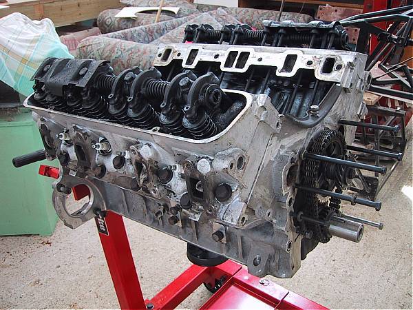
The timing chain was very slack but this is not unsurprising since the motor has done 110,000 miles. So I have decided to replace that with a new item, changing the cam gear and crank gear at the same time.
My intention was to use the timing cover from the 3.9 since it would allow me to use the better distributor and higher rate oil pump. Problem is the the Range Rover item is taller by virtue of having the water pump raised and offset to the offside. I'm not sure if this is going to cause the water pump pulley to hit the front upper chassis member. It also means that I would need to use the RR pulleys. The RR crank pulley is a larger in diameter than the P6 and again this might cause problems by hitting the lower front chassis member.
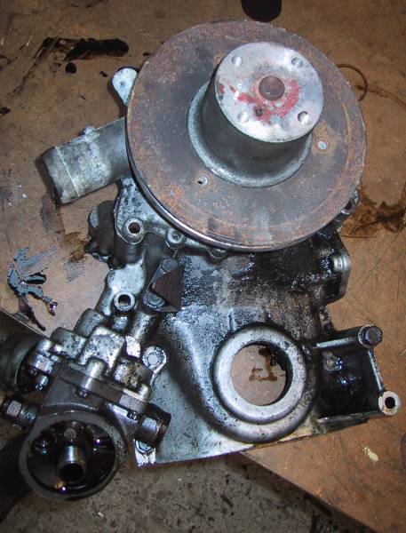
So in order not to delay the build, I am going to go with the RR front timing cover and water pump. I will then try to fit the P6 pulley system. This will probably mean some spacers here and there but it does mean that I get to use the P6 alternator mount which I'm told is ideal for the Rush. This approach also means that I avoid the nasty rope crank front oil seal in favour of the more modern item on the RR front cover
22nd April, 2001
The previously mentioned items arrived from Rimmer Bros and RPI, the wallet now being considerably lighter. I opted for the lightened and balanced flywheel option from RPI. The standard item weighs in at 31lb and I decided to go for the medium weight reduction of the 26lb item (they do go as low as 20lb).
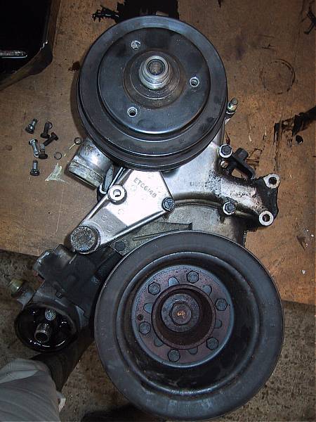
Otherwise this weekend was spent painting various items prior to fitting to the engine as well as fitting the new timing chain, sprockets and RR front cover.
The RR front cover is still causing me concern over its water pump height and position. Spent a lot of time today measuring the engine bay to see whether or not I am barking up the wrong tree (or just plain old barking!).
It looks like it will go with the following pulley & mounting combination, using one drivebelt only (hopefully):-
-
RR rearmost water pump pulley only.
-
RR crank pulley shaft with rear most crank pulley from the P6, reversed, and put onto the front of the RR item.
-
RR alternator mount (with slight modifications) and alternator, unusually mounted on the n/s of the engine. This is because the P6 alternator mount will not fit behind the RR waterpump housing without extreme modifications and would put the drivebelt in an unworkable position (assuming one belt only).
The above will put the crank pulley very close to the rigid front brake line that is mounted on the lower chassis cross member (as shown in the Dax manual.....). Looks like I will have to subtly reroute this prior to fitting the crank pulley. I seem to remember that Tim routed his differently to avoid this problem.
Its very close to engine in time now, just need to fit the gearbox etc. to the engine and away we go!. Still need to order the required gearbox mounting from Dax before in can proceed (as well as buy and fit a clutch slave cylinder). There is also the minor matter of fitting the driver's side footwell end panel now that I have bought some more aluminium to replace the original item 'butchered' on my first attempt!
23rd April, 2001
Managed to get another afternoon working on the Rush using up some time owed by working Easter Sunday.
First off, I fitted the driver's side footwell end panel. After my previous botched attempt, this time I made a cardboard template first and then cut the aluminium to match. The replacement aluminium was a slightly lighter gauge than the type supplied by Dax. This made it easier to warp the panel into position without leaving any obvious bend marks.
Trev's suggestion:- In order to make the footwell end panels easier to fit, you might like to consider using a lighter gauge aluminium in order to make working the panel into position less onerous.
Following the success of this (if you can call it that, ending up as I did with more Wurth on my hands than the panel I was fitting - that stuff is truly the Devil's own work) I set about rerouting the front transverse brake pipe. This took a little time since I did not wish to overwork the pipe leading to a possible fracture. This time I routed it along the front edge of the lower chassis cross member.
Tim e-mailed me today saying that contrary to what I had suggested on the 22nd April, he had simply followed a revised issue of the brake pipe routing diagram. It would seem that there are several updates & revisions to the Rush manual which I perhaps do not have. I'll get straight on the 'phone to the factory asking for these upon my return from Spain (otherwise I will contact Duncan who has a copy of the latest manual kindly donated to DROC by DJ Sportscars).
Trev's tip:- Regularly check with Dax to ensure that you have the most up-to-date issues of build drawings etc.
Final job today was to remove the automatic crankshaft spigot bush and replace it with a manual one (smaller inside diameter). Removing the old item turned out to be easier than I had hoped. Following a suggestion from my brother-in-law, I 'hydraulicked' the offending item out. That is to say I filled the aperture behind and through the spigot bush with grease. I then selected a socket that just fitted inside the bush and together with a short extension, I hit the socket into the bush with a 6lb lump hammer! The effect is to create a huge pressure behind the bush forcing it out. It came out fully on the third whack. Fitting the new bush was as simple as tapping it in.
Trev's tip:- Use grease and a tight fitting socket to 'hydraulic' an old crankshaft spigot bush out of the rear of the crankshaft.
Off to Barcelona on Tuesday so no work will be done now until May, c'est la vie!